
On this page
- 30 Tons per Day Sludge Treatment Project
- Ultra-High-Pressure Hydraulic Pressing Implementation Plan
- Chapter 1 – Project Overview
- Chapter 2 – Investment Estimation
- Chapter 3 – Operating Cost Analysis
- Chapter 4 – Equipment Description
- 4.4 Ultra-High-Pressure Dewatering Principle
- 4.5 Main Equipment Parameters
- Chapter 5 – Process Flow
- Chapter 6 – Electrical & Control System
- Chapter 7 – Conclusion
- Chapter 8 – Electrical & Control System
- 8.1 General Description
- 8.2 Electrical Control System Configuration
30 Tons per Day Sludge Treatment Project
Ultra-High-Pressure Hydraulic Pressing Implementation Plan
Date: July 2, 2024
Chapter 1 – Project Overview
1.1 Project Information
1.1.1 Project Name
30 Tons per Day Sludge Hydraulic Dewatering Project
1.1.2 Implementing Company
Shandong Shengshi Hecheng Machinery Co., Ltd.
1.1.3 Project Construction Period
- Construction start: July 2024
- Total duration: 90 working days
Chapter 2 – Investment Estimation
Based on the existing facilities and equipment at the plant site, the project follows the principle of:
“Maximizing the utilization of existing facilities and process systems, minimizing additional investment, and achieving system upgrading through optimized configuration.”
This project mainly involves process optimization, equipment upgrading, and the addition of the following equipment:
- Mixing tank
- Automatic sludge feeding machine
- Automatic material spreading & cake discharge machine
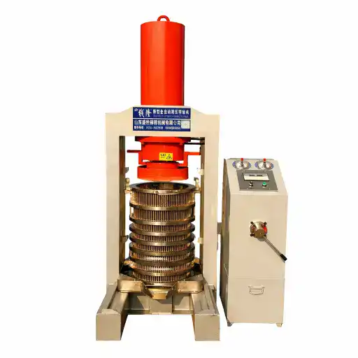
- Ultra-high-pressure hydraulic press
- Operation platform
- Filter cloth system
- Electrical automatic control system
- Hydraulic control system
- Spreading machine control system
- Ultra-high-pressure pump station
- Filter press material barrel
- Wastewater pump
- Sludge cake conveying system
- Sludge piston pump
- Chemical dosing machine
- Conditioning mixer (18 kW)
- Transportation cost
- Installation and commissioning cost
Detailed Equipment Investment List
Table 1 – Equipment Investment Budget
| No. | Equipment Name | Model / Specification | Unit | Qty | Unit Price (RMB) | Total (RMB) | Material |
|---|---|---|---|---|---|---|---|
| 1 | Mixing Tank | 10 m³ | Set | 1 | 50,000 | 50,000 | Carbon steel |
| 2 | Automatic Feeding Machine | 2 m³ | Unit | 1 | 22,000 | 22,000 | Carbon steel |
| 3 | Automatic Spreading & Cake Discharge Machine | 1000 Type | Unit | 1 | 65,000 | 65,000 | Stainless steel chain plate + carbon steel frame |
| 4 | Ultra-High-Pressure Press | 800 Type | Unit | 1 | 195,000 | 195,000 | Carbon steel |
| 5 | Filter Press Material Barrel | 1×1×2 m | Unit | 1 | 60,000 | 60,000 | Carbon steel |
| 6 | Operation Platform | — | Unit | 1 | 30,000 | 30,000 | Carbon steel |
| 7 | Filter Cloth | — | Set | 2 | 3,500 | 7,000 | 440 m filter cloth |
| 8 | Electrical Control System (Spreader) | 1000 Type | Set | 1 | 68,000 | 68,000 | Siemens components |
| 9 | Hydraulic Control System | 800 Type | Set | 1 | 26,000 | 26,000 | Siemens components |
| 10 | Ultra-High-Pressure Pump Station | 60 Type | Set | 1 | 56,000 | 56,000 | Max pressure 150 MPa |
| 11 | Wastewater Pump | 15 | Unit | 1 | 2,700 | 2,700 | Carbon steel |
| 12 | Horizontal Sludge Piston Pump | 10 m³ | Set | 2 | 56,000 | 56,000 | Carbon steel |
| 13 | Sludge Cake Conveyor | 10 m | Meter | 10 | 2,000 | 20,000 | Belt conveyor |
| 14 | Chemical Dosing Machine | 66 Type | Unit | 1 | 30,000 | 30,000 | Carbon steel |
| 15 | Conditioning Mixer | 2 m³ | Unit | 1 | 20,000 | 20,000 | Carbon steel |
| 16 | Transportation Cost | — | — | — | — | — | Based on distance |
| 17 | On-site Installation & Commissioning | — | — | — | 60,000 | 60,000 | — |
Total Investment:
RMB 812,700 (excluding tax and transportation)
Chapter 3 – Operating Cost Analysis
3.1 Labor Cost
- RMB 200 / person / day
3.2 Electricity Cost
- 24 hours operation per unit
- Approx. 720 kWh/day
- Electricity price: RMB 0.6 / kWh
- Daily electricity cost: RMB 432
Daily Operating Cost Summary
| Item | Cost (RMB/day) |
|---|---|
| Labor (3 persons) | 900 |
| Electricity | 432 |
| Water | 0 |
| Miscellaneous | 50 |
| Total | 1,382 |
Unit processing cost:
- RMB 46 per ton (based on 30 tons/day)
Chapter 4 – Equipment Description
4.1 Technology Overview
This project adopts the Ultra-High-Pressure Hydraulic Dewatering & Volume Reduction Technology.
The system uses self-developed ultra-high-pressure hydraulic pressing equipment with PLC automatic control, significantly improving operational efficiency and stability.
4.2 Treatment Effect
- Moisture content reduced from 85% to below 50%
- Mechanical pressing only, no thermal drying
- Stable and continuous operation
4.3 Process Description
- Sludge with 85% moisture content is transferred from the buffer tank via screw pump to the spreading machine.
- Sludge is layered between double filter cloths and transferred to the oscillating distributor.
- The filled material barrel is pushed into the ultra-high-pressure hydraulic press.
- After pressing, the press returns and the barrel is pulled out.
- The top cake cylinder pushes the sludge cake upward.
- Filter cloth is automatically recovered.
- Sludge cake is crushed and collected.
The system adopts cyclic operation, allowing two stations to operate simultaneously (feeding, pressing, discharging).
4.4 Ultra-High-Pressure Dewatering Principle
The system uses ultra-high hydraulic pressure to overcome the limitations of belt presses, screw presses, and plate-frame presses.
By continuous high-pressure extrusion:
- Free water and bound water are separated
- Sludge cake does not reabsorb water
- Secondary utilization becomes feasible
4.5 Main Equipment Parameters
(1) Storage Tank
- Material: Carbon steel
- Thickness: 5 mm
- Diameter: 1.5 m
- Height: 3 m
- Motor power: 7.5 kW
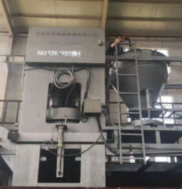
(2) Ultra-High-Pressure Hydraulic Press (Model: YY800)
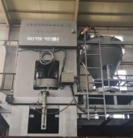
- Main pressing force: 800 tons
- Main cylinder material: 27SiMn alloy steel
- Working pressure: 45 MPa
- Pressing stroke: 1.5 m
- Top cake cylinder force: 60 tons
- Top cake cylinder stroke: 2 m
- Barrel volume: 2 m³
- Power consumption: 21 kW/h
- Machine size: 6 × 3 × 9 m
- Power supply: 380V / 50Hz
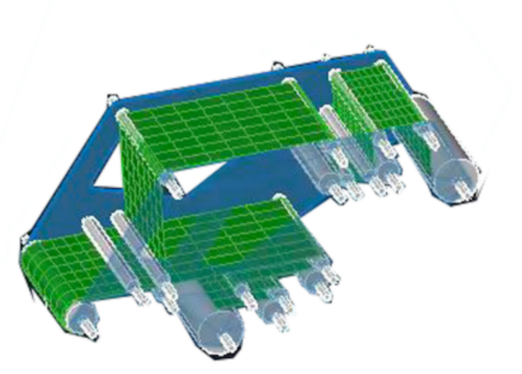
(3) Material Spreading Machine
- Filter cloth width: 1000 mm
- Total power: 9 kW
- PLC-controlled automatic operation
- Carbon steel 355B structure
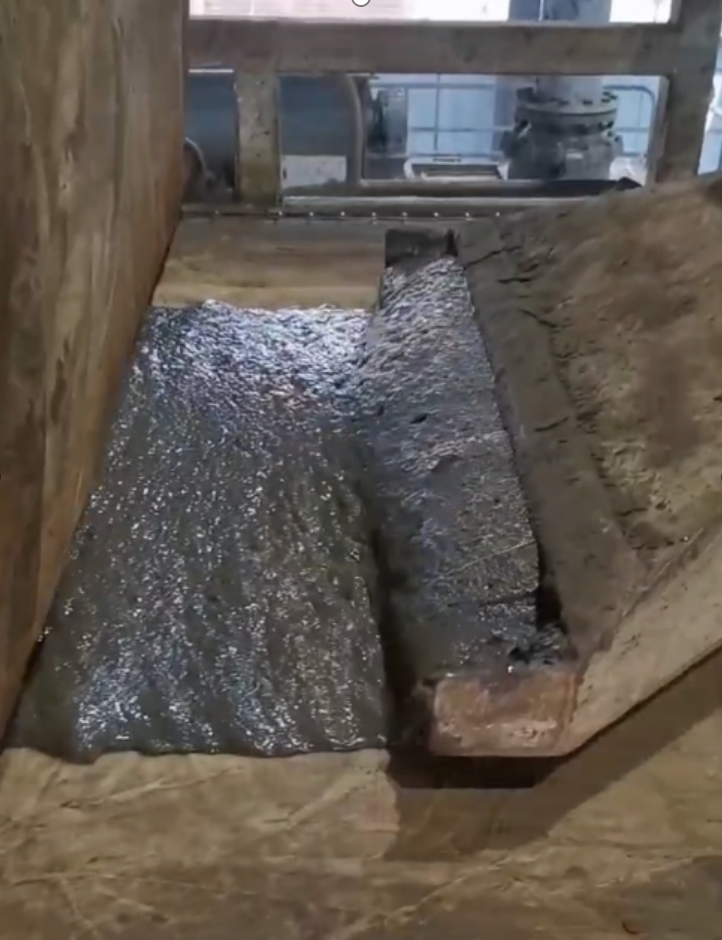
(4) Swing Distributor
(4) Swing Distributor
- Distribution width: 1100 mm
- Motor power: 2.2 kW
- Automatic torque-based speed adjustment
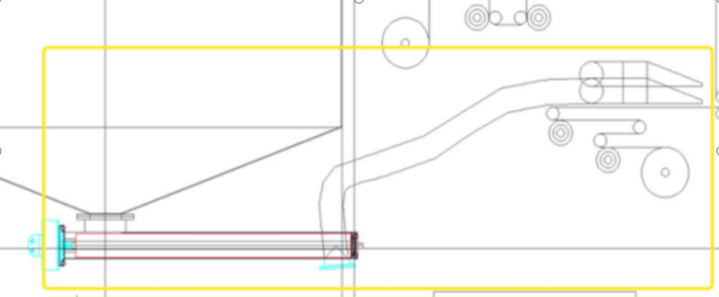
(5) Automatic Feeding Machine
- Hydraulic drive
- Motor power: 15 kW
- Max conveying capacity: 10 t/h
Chapter 5 – Process Flow
Operation Platform → Mixing Tank → Automatic Feeding → Spreading → Ultra-High-Pressure Pressing → Cake Discharge
Chapter 6 – Electrical & Control System
- Siemens PLC (S7 series)
- Siemens HMI touch screen
- Siemens VFDs
- Distributed sensors and pressure transmitters
- Fully automatic operation with manual override
Chapter 7 – Conclusion
The Ultra-High-Pressure Hydraulic Dewatering System provides a high-efficiency, low-energy, and reliable solution for sludge and digestate treatment, enabling downstream resource utilization and long-term stable operation.
Chapter 8 – Electrical & Control System
8.1 General Description
The electrical and control system of this project is designed in accordance with the principles of safety, reliability, automation, and ease of operation.
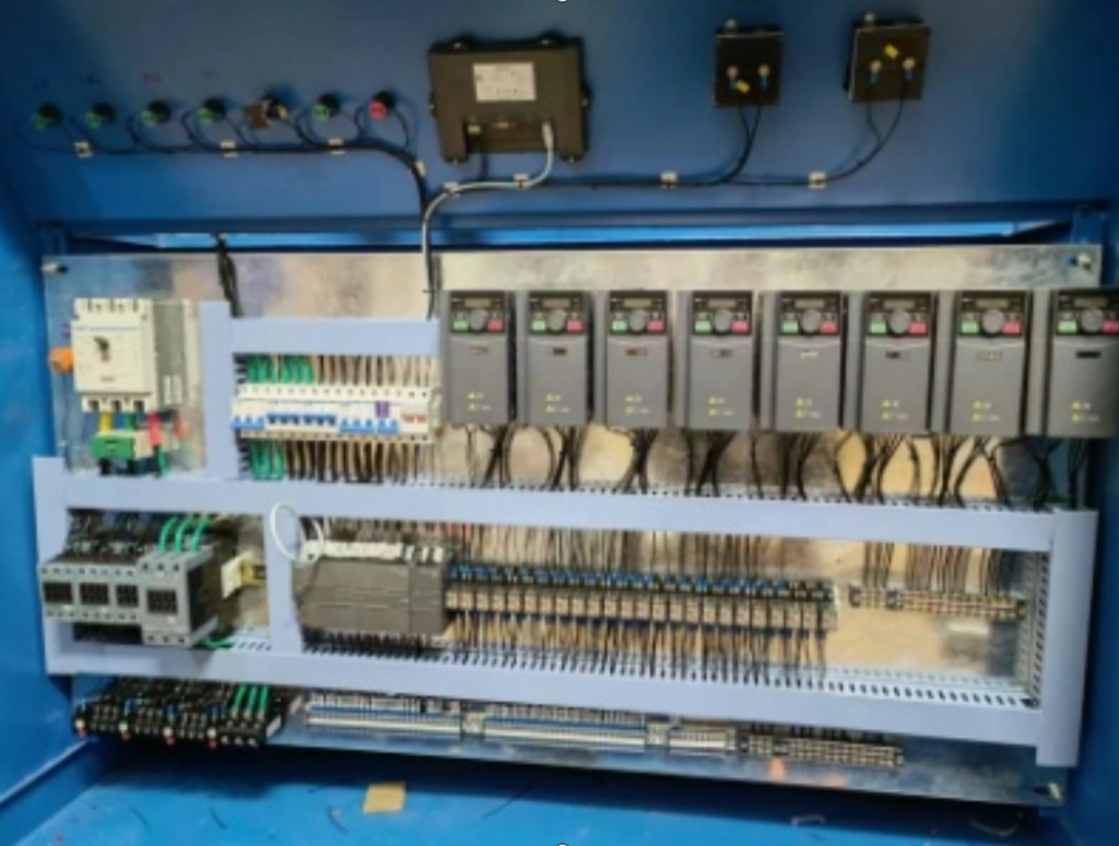
The system adopts a centralized PLC control architecture, integrating sludge feeding, spreading, ultra-high-pressure hydraulic pressing, cake discharge, chemical dosing, and auxiliary systems into one unified control platform.
All electrical components are selected from internationally recognized first-tier brands, ensuring long service life, stable operation, and convenient maintenance.
8.2 Electrical Control System Configuration
Table 8-1 – Electrical Control System Specification
| Item | Description |
|---|---|
| Control Mode | PLC centralized automatic control |
| Operation Mode | Automatic / Manual selectable |
| Control Cabinet | Independent electrical control cabinet |
| Cabinet Material | Carbon steel cabinet with protective coating |
| Protection Level | IP54 |
| Control Voltage | 24 V DC |
| Power Supply | AC 380 V / 50 Hz |
| Grounding System | Independent protective grounding |
| Emergency Stop | Installed at key operation positions |
| Signal Transmission | Shielded industrial control cables |
| System Expansion | Reserved I/O and communication interfaces |
The electrical cabinet is equipped with complete protection functions including short-circuit protection, overload protection, phase loss protection, and emergency shutdown.
8.3 PLC Control System
The core control system adopts a Siemens PLC platform, ensuring high reliability and strong anti-interference capability.
Main PLC Configuration
- PLC brand: Siemens
- PLC series: S7 series
- Control method: Centralized control + distributed signal acquisition
- Communication protocol: Industrial standard fieldbus communication
PLC Functions
- Automatic sequence control of the entire dewatering process
- Real-time monitoring of pressure, position, and operating status
- Automatic interlock protection between equipment
- Fault diagnosis and alarm output
- Data storage and historical record function
8.4 Human–Machine Interface (HMI)
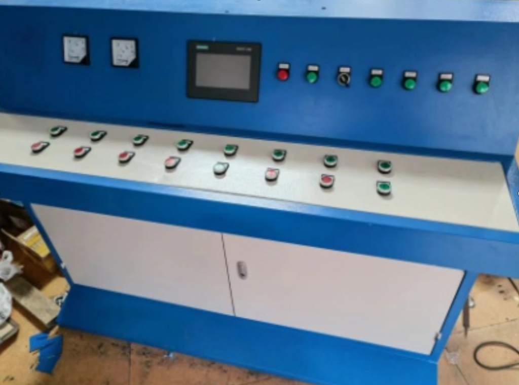
The system is equipped with a Siemens touch screen HMI, installed on the main electrical cabinet.
HMI Functions
- Real-time display of system operating status
- Display of hydraulic pressure, cylinder position, and process parameters
- Manual/automatic mode switching
- Alarm display and fault information
- Parameter setting and modification (password protected)
The HMI interface is designed with clear logic, intuitive graphics, and simple operation, suitable for on-site operators with minimal training.
8.5 Variable Frequency Drive (VFD) System
All motors with speed regulation requirements are equipped with Siemens variable frequency drives (VFDs).
VFD Characteristics
- Soft start and soft stop
- Energy saving operation
- Torque control function
- Overload, overcurrent, and overtemperature protection
- Communication with PLC for centralized control
The VFD system significantly reduces mechanical impact during startup and improves overall system stability.
8.6 Sensor and Instrumentation System
The system is equipped with a complete set of industrial sensors to ensure accurate monitoring and safe operation.
Main Instruments
- Pressure transmitters (hydraulic system)
- Limit switches (position detection)
- Proximity sensors
- Level sensors (material tanks)
- Temperature sensors (hydraulic oil system)
All sensors provide real-time feedback to the PLC system for closed-loop control and safety interlock.
8.7 Safety Protection Measures
The electrical system includes multiple layers of safety protection:
- Emergency stop buttons installed at critical operation points
- Overpressure protection of hydraulic system
- Electrical interlock to prevent misoperation
- Automatic shutdown in case of abnormal signals
- Manual override for emergency operation
These measures ensure operator safety and equipment protection during long-term operation.
Chapter 9 – Control & Operation Advantages
9.1 Overall Control Philosophy
The control system is designed to achieve:
- High automation level
- Reduced manual intervention
- Stable and repeatable dewatering results
- Easy operation and maintenance
Table 9-1 – Control & Operation Advantages
| Item | Description |
|---|---|
| Automation Level | Fully automatic operation after startup |
| Operation Mode | Manual / Semi-automatic / Automatic |
| Operator Requirement | Low labor intensity, simple training |
| Process Stability | Stable pressure and uniform cake quality |
| Alarm System | Visual and audible alarms |
| Data Monitoring | Real-time and historical data |
| Fault Handling | Automatic protection and alarm prompting |
9.2 Operation Process Control
Once the system is started in automatic mode:
- Sludge feeding
- Material spreading
- Hydraulic pressing
- Pressure holding
- Cake discharge
- Filter cloth recovery
are all completed automatically according to the preset program without manual intervention.
9.3 Fault Diagnosis and Alarm System
The PLC system continuously monitors:
- Hydraulic pressure
- Motor status
- Sensor signals
- Electrical faults
When abnormal conditions occur, the system will:
- Automatically stop the corresponding equipment
- Display fault information on the HMI
- Trigger audible and visual alarms
Chapter 10 – Chemical Dosing System & Control
10.1 Chemical Dosing System Overview
The chemical dosing system is used to improve sludge conditioning performance before hydraulic pressing.
It consists of:
- Chemical dosing tank
- Dosing pump
- Mixing system
- Electrical control system
Table 10-1 – Chemical Dosing Electrical Control Configuration
| Item | Description |
|---|---|
| Control Mode | PLC automatic control |
| Dosing Adjustment | Manual / Automatic |
| Pump Type | Diaphragm dosing pump |
| Mixing Control | Automatic timing control |
| Signal Feedback | Flow and running status |
| Safety Protection | Dry-run and overload protection |
The dosing system operates in coordination with the sludge feeding system to ensure stable conditioning effect.
10.2 Control Logic
- Chemical dosage can be adjusted through HMI
- Automatic start/stop linked with sludge feeding
- Alarm triggered in case of abnormal dosing
Chapter 11 – Water Supply, Drainage & Odor Control
11.1 Water Supply System
- Cleaning water for filter cloth and equipment
- Recycled process water prioritized
- No fresh water consumption during normal operation
11.2 Drainage System
- Filtrate water collected centrally
- Returned to upstream wastewater treatment system
- No direct discharge to environment
11.3 Odor Control Measures
Odor sources mainly originate from:
- Sludge storage
- Sludge conditioning
Control measures:
- Fully enclosed system
- Centralized exhaust collection
- Deodorization treatment
Emission Standards
- GB14554-93 – Emission Standard for Odor Pollutants
- DB12/059-2018 – Local Environmental Standard
Chapter 12 – Operating Cost Analysis
Table 12-1 – Operating Cost per Ton of Sludge
| Item | Cost (RMB / ton) |
|---|---|
| Electricity | 5.0 |
| Chemicals | 20.0 |
| Labor | 6.5 |
| Maintenance | 2.5 |
| Consumables | 1.5 |
| Total | 35.5 |
Chapter 13 – Complete Equipment List (Full Translation)
Table 13-1 – Main Equipment List
| No. | Equipment Name | Quantity |
|---|---|---|
| 1 | Sludge Receiving System | 1 set |
| 2 | Conditioning & Mixing System | 1 set |
| 3 | Ultra-High-Pressure Hydraulic Press | 1 unit |
| 4 | Hydraulic Pump Station | 1 set |
| 5 | Automatic Spreading System | 1 set |
| 6 | Electrical Control System | 1 set |
| 7 | Conveying System | 1 set |
Total Investment: RMB 1.5 million (excluding tax and transportation)
Chapter 14 – Electrical Component Brand List
- PLC: Siemens
- HMI: Siemens
- VFD: Siemens
- Low-voltage electrical components: Siemens or equivalent
- Sensors: Industrial-grade international brands
Chapter 15 – Hydraulic System
15.1 Hydraulic System Overview
The hydraulic system is the core power unit of the ultra-high-pressure dewatering equipment.
It provides stable, continuous, and controllable pressure required for sludge compression, cake discharge, and auxiliary movements.
The system is designed based on the principles of:
- High pressure stability
- Reliable long-term operation
- Precise pressure control
- Safe and simple maintenance
The hydraulic system works in full coordination with the electrical PLC control system to ensure precise execution of each operating step.
15.2 Hydraulic System Composition
The hydraulic system consists of the following main components:
- Ultra-high-pressure hydraulic pump station
- Main pressing hydraulic cylinder
- Top cake discharge hydraulic cylinder
- Hydraulic oil tank
- Control valve group
- Pressure regulating system
- Oil filtration and cooling system
- Hydraulic pipeline system
- Safety protection devices
15.3 Ultra-High-Pressure Hydraulic Pump Station
15.3.1 Pump Station Description
The ultra-high-pressure pump station is the power source of the entire hydraulic system.
It adopts a high-pressure plunger pump structure, capable of delivering continuous and stable hydraulic pressure.
Main Parameters
- Maximum working pressure: 150 MPa
- Rated working pressure: 45 MPa
- Drive mode: Electric motor drive
- Control mode: PLC-controlled automatic operation
- Pressure regulation: Proportional pressure control
The pump station is equipped with multiple protection mechanisms to ensure safe operation under high-pressure conditions.
15.4 Hydraulic Cylinders
15.4.1 Main Pressing Cylinder
The main pressing cylinder is responsible for generating the ultra-high compressive force required for sludge dewatering.
Technical Parameters
- Maximum pressing force: 800 tons
- Cylinder material: 27SiMn high-strength alloy steel
- Piston rod surface treatment: Hard chrome plating
- Working pressure: 45 MPa
- Stroke length: 1.5 m
The cylinder body is precision-machined and pressure-tested to ensure no leakage and long service life.
15.4.2 Top Cake Discharge Cylinder
The top cake cylinder is used to push the compressed sludge cake out of the pressing chamber after the pressing process is completed.
Technical Parameters
- Maximum thrust force: 60 tons
- Working pressure: 20 MPa
- Stroke length: 2.0 m
This cylinder ensures smooth and complete cake discharge without damaging the filter cloth.
15.5 Hydraulic Valve System
The hydraulic valve system controls:
- Direction of oil flow
- Pressure regulation
- Flow rate adjustment
Valve Configuration
- Directional control valves
- Pressure relief valves
- Proportional pressure regulating valves
- Check valves
All valves are designed for high-pressure applications and selected from reliable industrial-grade manufacturers.
15.6 Pressure Control & Regulation
The system adopts multi-stage pressure control logic:
- Low-pressure rapid closing stage
- Medium-pressure pre-pressing stage
- High-pressure dewatering stage
- Pressure holding stage
- Pressure release stage
Pressure values for each stage can be:
- Preset in PLC
- Adjusted through HMI interface
This staged pressure control ensures maximum water removal while protecting equipment and filter cloth.
15.7 Hydraulic Oil System
15.7.1 Hydraulic Oil Tank
- Material: Carbon steel
- Volume: Designed to meet continuous operation requirements
- Oil level monitoring: Level gauge + alarm
15.7.2 Oil Filtration System
- Return oil filtration
- Suction oil filtration
- Filtration accuracy ensures clean oil circulation
Regular filtration effectively extends the service life of hydraulic components.
15.7.3 Oil Cooling System
- Natural air cooling
- Optional forced cooling based on operating conditions
Oil temperature is monitored to prevent overheating during continuous operation.
15.8 Hydraulic Pipeline System
- High-pressure seamless steel pipes
- Flexible hose connections at vibration points
- All pipelines pressure-tested before commissioning
Pipeline layout follows the principles of:
- Short flow paths
- Minimal pressure loss
- Easy inspection and maintenance
15.9 Safety Protection of Hydraulic System
The hydraulic system includes multiple safety protections:
- Main pressure relief valve to prevent overpressure
- Pressure sensors with PLC interlock
- Emergency stop automatic pressure unloading
- Manual pressure release function
- Oil temperature and oil level alarms
These protections ensure safe and reliable operation under ultra-high-pressure conditions.
15.10 Hydraulic System Operating Cycle
- Pump station startup
- Main cylinder forward movement
- Pressure buildup according to preset curve
- Pressure holding for dewatering
- Pressure release
- Main cylinder return
- Top cake cylinder discharge
- System reset for next cycle
This cycle is fully automatic and synchronized with the electrical control system.
15.11 Hydraulic System Advantages
- Ultra-high pressure capability
- Stable pressure output
- Precise control
- Long service life
- Low failure rate
- Easy maintenance
The hydraulic system is designed for continuous industrial operation and meets long-term sludge dewatering requirements
Chapter 16 – Installation, Commissioning & Acceptance
16.1 Installation Overview
The installation of the ultra-high-pressure hydraulic dewatering system shall be carried out in strict accordance with the approved design drawings, technical specifications, and relevant national and industrial standards.
Installation work shall follow the principles of:
- Safety first
- Standardized construction
- Coordinated installation
- Step-by-step verification
All installation works shall be completed by qualified technicians under the guidance of the equipment supplier.
16.2 Installation Conditions
Before installation, the following conditions shall be met:
- Civil foundations and embedded parts have been completed and accepted
- Equipment foundation strength meets design requirements
- Power supply, water supply, and drainage systems are available
- Installation area is clean, flat, and free of obstacles
- Lifting equipment and installation tools are ready
- Technical documents and drawings are complete
16.3 Equipment Installation Procedure
16.3.1 Main Equipment Installation
- Position and level the ultra-high-pressure hydraulic press according to layout drawings
- Fix the press base using anchor bolts
- Install the main pressing cylinder and top cake discharge cylinder
- Install the material barrel and pressing chamber
- Install the operation platform and safety guards
Alignment and leveling accuracy shall meet equipment technical requirements.
16.3.2 Hydraulic System Installation
- Install hydraulic pump station on designated foundation
- Connect hydraulic oil pipelines according to hydraulic schematic
- Install control valves, pressure sensors, and safety valves
- Flush hydraulic pipelines before oil filling
- Fill hydraulic oil to specified level
All pipelines shall be pressure-tested to ensure no leakage.
16.3.3 Electrical System Installation
- Install electrical control cabinet at designated position
- Connect main power cables and grounding system
- Install field sensors, motors, and actuators
- Complete cable wiring and labeling
- Check insulation resistance and grounding continuity
Electrical installation shall comply with national electrical standards.
16.4 Installation Quality Control
- Equipment positioning deviation shall not exceed design tolerance
- Hydraulic pipeline connections shall be tight and leak-free
- Electrical wiring shall be neat, labeled, and protected
- All fasteners shall be tightened to specified torque
- Safety guards and warning signs shall be properly installed
Installation quality shall be inspected and recorded at each stage.
16.5 Commissioning Overview
Commissioning aims to verify:
- Mechanical integrity
- Electrical control logic
- Hydraulic system performance
- Process operation reliability
Commissioning shall be carried out step-by-step, from single equipment to full system operation.
16.6 No-Load Commissioning
16.6.1 Electrical System Test
- Power-on inspection
- PLC and HMI startup verification
- Manual/automatic mode switching test
- Sensor signal verification
- Alarm and interlock testing
16.6.2 Hydraulic System Test
- Start hydraulic pump station
- Check oil pressure, oil temperature, and noise
- Test directional valves and pressure regulation
- Check cylinder movement and stroke limits
- Verify pressure relief and safety functions
No-load operation shall run continuously without abnormal vibration or leakage.
16.7 Load Commissioning
16.7.1 Initial Feeding Test
- Introduce sludge gradually into the system
- Observe feeding, spreading, and pressing processes
- Adjust pressure parameters according to sludge characteristics
16.7.2 Continuous Operation Test
- Operate system continuously under design load
- Monitor moisture content of sludge cake
- Observe system stability and automation performance
The system shall achieve:
- Stable moisture reduction to design target
- Continuous and reliable operation
- Normal discharge of filtrate and sludge cake
16.8 Performance Verification
During commissioning, the following indicators shall be verified:
- Processing capacity: ≥ 30 tons/day
- Outlet moisture content: ≤ 50%
- Equipment operation stability
- Automation level and control accuracy
Test results shall be recorded and signed by both parties.
16.9 Acceptance Criteria
16.9.1 Mechanical Acceptance
- Equipment installation meets design drawings
- No abnormal vibration or noise
- All moving parts operate smoothly
16.9.2 Electrical Acceptance
- Control logic operates correctly
- Safety interlocks function properly
- Alarm and protection systems are effective
16.9.3 Process Acceptance
- Dewatering performance meets design requirements
- Sludge cake quality is stable
- Filtrate discharge is normal
16.10 Final Acceptance
Final acceptance shall be conducted after continuous trial operation.
Acceptance documents include:
- Equipment installation records
- Commissioning and test reports
- Performance verification data
- Operation and maintenance manuals
- Training records
After acceptance, the system shall be formally handed over to the owner for operation.
16.11 Training and Handover
The equipment supplier shall provide on-site training, including:
- Equipment operation
- Daily inspection
- Routine maintenance
- Emergency handling
Training ensures operators can independently operate and maintain the system.
16.12 Safety Requirements During Installation & Commissioning
- Strict compliance with safety operation procedures
- Personnel must wear protective equipment
- High-pressure systems shall not be adjusted under load
- Unauthorized operation is strictly prohibited
Chapter 17 – Operation, Maintenance (O&M) and Servicing
17.1 General O&M Principles
The operation and maintenance of the ultra-high-pressure hydraulic dewatering system shall follow the principles of:
- Safe operation
- Preventive maintenance
- Planned servicing
- Continuous and stable performance
Proper operation and routine maintenance are essential to ensure:
- Long service life of equipment
- Stable dewatering efficiency
- Reduced failure rate
- Lower overall operating cost
Only trained and authorized personnel are permitted to operate and maintain the system.
17.2 Daily Operation Requirements
17.2.1 Pre-Start Inspection
Before starting the system, operators shall check the following items:
- Hydraulic oil level is within the normal range
- No visible oil leakage in hydraulic pipelines and joints
- Electrical control cabinet is clean and dry
- Emergency stop buttons are in normal status
- Filter cloth is properly installed and tensioned
- No foreign objects in moving parts area
The system shall not be started if any abnormal condition is detected.
17.2.2 Startup Procedure
- Switch on main power supply
- Start electrical control system and PLC
- Start hydraulic pump station
- Select operation mode (manual or automatic)
- Start sludge feeding system
- Enter normal pressing cycle
Startup shall follow the prescribed sequence to prevent equipment damage.
17.2.3 Normal Operation Monitoring
During operation, operators shall continuously monitor:
- Hydraulic pressure curve
- Oil temperature and oil level
- Motor running current
- Sludge feeding condition
- Cake discharge status
- Alarm and fault information
Any abnormal condition shall be handled immediately according to operating procedures.
17.2.4 Shutdown Procedure
- Stop sludge feeding
- Complete current pressing cycle
- Release hydraulic pressure
- Stop hydraulic pump station
- Switch off electrical control system
- Cut off main power supply
Sudden shutdown under high pressure is strictly prohibited unless in emergency situations.
17.3 Routine Maintenance Schedule
17.3.1 Daily Maintenance
- Clean equipment surface and operating area
- Check hydraulic oil level
- Check for oil leakage
- Clean filter cloth and surrounding area
- Record operating data and abnormalities
17.3.2 Weekly Maintenance
- Check tightness of bolts and fasteners
- Inspect hydraulic pipelines and fittings
- Test emergency stop and safety interlocks
- Check motor and pump noise and vibration
17.3.3 Monthly Maintenance
- Inspect hydraulic oil quality
- Check oil filters and clean or replace if necessary
- Inspect electrical connections and terminals
- Check sensor accuracy and signal stability
17.3.4 Annual Maintenance
- Replace hydraulic oil completely
- Replace hydraulic oil filters
- Inspect main hydraulic cylinders for wear
- Inspect seals and replace if necessary
- Perform full system inspection and performance assessment
17.4 Hydraulic System Maintenance
17.4.1 Hydraulic Oil Management
- Use specified grade hydraulic oil only
- Maintain oil cleanliness level
- Avoid oil contamination during filling
- Monitor oil temperature during operation
Oil replacement interval shall not exceed 12 months under normal operating conditions.
17.4.2 Hydraulic Cylinder Maintenance
- Regularly inspect cylinder surface and seals
- Prevent dust and debris accumulation
- Do not operate cylinder beyond rated pressure
Any abnormal leakage or vibration shall be addressed immediately.
17.5 Electrical System Maintenance
- Keep electrical cabinet clean and dry
- Check grounding connections regularly
- Inspect cable insulation
- Backup PLC program periodically
- Do not modify control parameters without authorization
Electrical maintenance shall be performed by qualified electricians only.
17.6 Filter Cloth Maintenance
- Clean filter cloth after each operation cycle
- Prevent damage from sharp objects
- Replace filter cloth when filtration efficiency decreases
- Keep spare filter cloths in clean and dry storage
Proper filter cloth maintenance directly affects dewatering performance.
17.7 Spare Parts Management
Recommended spare parts include:
- Hydraulic seals
- Filter cloth
- Pressure sensors
- Electrical relays
- Limit switches
Spare parts shall be stored in a dry and clean environment.
17.8 Common Faults and Troubleshooting
17.8.1 Insufficient Dewatering Effect
Possible causes:
- Low hydraulic pressure
- Clogged filter cloth
- Improper sludge conditioning
Corrective actions:
- Adjust pressure settings
- Clean or replace filter cloth
- Optimize chemical dosing
17.8.2 Hydraulic Pressure Fluctuation
Possible causes:
- Air in hydraulic system
- Oil contamination
- Valve malfunction
Corrective actions:
- Bleed air from system
- Replace hydraulic oil
- Inspect and repair valves
17.8.3 Electrical Alarm
Possible causes:
- Sensor failure
- Motor overload
- Communication fault
Corrective actions:
- Check sensor wiring
- Inspect motor load
- Reset system and diagnose PLC alarm
17.9 Safety Precautions During O&M
- Never perform maintenance under pressure
- Lock out and tag out power supply before servicing
- Wear appropriate personal protective equipment
- Follow standard safety procedures strictly
17.10 Record Keeping
Operators shall maintain the following records:
- Daily operation logs
- Maintenance records
- Fault and repair records
- Spare parts usage records
These records provide important references for long-term system optimization.
17.11 Service Life and Reliability
With proper operation and maintenance, the system is designed for:
- Long service life
- Stable performance
- Continuous industrial operation
Chapter 18 – Safety Operating Procedures & Emergency Handling
18.1 General Safety Principles
Safety is the highest priority during the operation, maintenance, and servicing of the ultra-high-pressure hydraulic dewatering system.
All personnel involved in operation and maintenance shall:
- Receive professional training
- Be familiar with system structure and operating procedures
- Strictly follow safety regulations
Unauthorized operation and violation of safety procedures are strictly prohibited.
18.2 Personnel Safety Requirements
- Operators must be trained and certified before independent operation
- Non-operating personnel are prohibited from entering the equipment operation area
- Personal protective equipment (PPE) must be worn, including:
- Safety helmet
- Protective gloves
- Safety shoes
- Eye protection when necessary
- Loose clothing and accessories are strictly prohibited during operation
18.3 Equipment Safety Requirements
- Safety guards and protective covers must be installed and intact
- Safety warning signs shall be clearly visible
- Emergency stop buttons must be accessible and functional
- Safety interlock systems shall not be bypassed or disabled
- Equipment shall not be operated beyond rated parameters
18.4 High-Pressure Hydraulic Safety Regulations
Due to the ultra-high-pressure characteristics of the system, the following rules must be strictly observed:
- Never loosen hydraulic fittings under pressure
- Do not inspect hydraulic pipelines during high-pressure operation
- Pressure adjustment is prohibited during pressurized operation
- Hydraulic pressure must be fully released before maintenance
- Only specified hydraulic oil shall be used
Failure to comply may result in serious personal injury or equipment damage.
18.5 Electrical Safety Regulations
- Electrical maintenance must be performed by qualified electricians
- Power supply must be locked and tagged out before maintenance
- Electrical cabinet doors must remain closed during operation
- Wet hands are prohibited from operating electrical equipment
- Grounding system must remain intact and effective
18.6 Safe Operating Procedures
18.6.1 Safe Startup
- Confirm all safety checks are completed
- Ensure no personnel remain in hazardous areas
- Start equipment according to prescribed startup sequence
18.6.2 Safe Operation
- Monitor operating parameters continuously
- Do not overload equipment
- Respond immediately to alarms and abnormal signals
- Do not leave the system unattended during operation
18.6.3 Safe Shutdown
- Stop feeding system first
- Complete current pressing cycle
- Release hydraulic pressure
- Shut down hydraulic and electrical systems in sequence
18.7 Emergency Handling Procedures
18.7.1 Emergency Stop
In case of emergency:
- Immediately press the nearest emergency stop button
- Cut off power supply
- Release hydraulic pressure automatically
- Evacuate personnel from danger zone
Emergency stop shall only be reset after fault clearance and safety confirmation.
18.7.2 Power Failure Emergency
In case of sudden power failure:
- The system will automatically stop
- Hydraulic pressure will be safely released
- Restart is prohibited until power is restored and system inspection is completed
18.7.3 Hydraulic System Emergency
Possible emergencies:
- Hydraulic oil leakage
- Abnormal pressure rise
- Hydraulic pump overheating
Emergency actions:
- Activate emergency stop
- Release system pressure
- Identify leakage or fault source
- Repair only after complete pressure release
18.7.4 Electrical System Emergency
Possible emergencies:
- Electrical short circuit
- Motor overload
- PLC or control failure
Emergency actions:
- Cut off main power supply
- Inspect electrical components
- Reset alarms only after troubleshooting
18.7.5 Fire Emergency
- Cut off power supply immediately
- Use appropriate fire extinguishers
- Do not use water on electrical fires
- Evacuate personnel and notify fire services
18.8 Environmental & Occupational Safety
- Ensure adequate ventilation in equipment room
- Prevent hydraulic oil and sludge leakage to environment
- Collect and dispose of waste materials properly
- Maintain clean and orderly working environment
18.9 Emergency Response Training
- Conduct regular emergency drills
- Train operators in emergency handling procedures
- Update emergency plans periodically
18.10 Accident Reporting and Analysis
In case of accidents:
- Report immediately to responsible personnel
- Preserve the scene and records
- Conduct accident investigation
- Implement corrective and preventive measures
18.11 Safety Documentation
The following documents shall be maintained:
- Safety operation manuals
- Emergency handling procedures
- Training records
- Accident reports
18.12 Safety Responsibility
- Equipment supplier: Provide technical guidance and safety training
- Owner/operator: Ensure compliance with safety regulations
- Operators: Strictly follow operating procedures
Safety responsibility is implemented at all levels.
Project planning
Configure the right oil press and production line
Send your oilseed, target output, bottle or packaging requirements, power supply, and destination country. We will match the machine, supporting equipment, and line layout.