TY-4 semi-automatic aluminium cap sealing machine
Roll-on aluminium and tamper-evident caps onto filled bottles, one bottle at a time
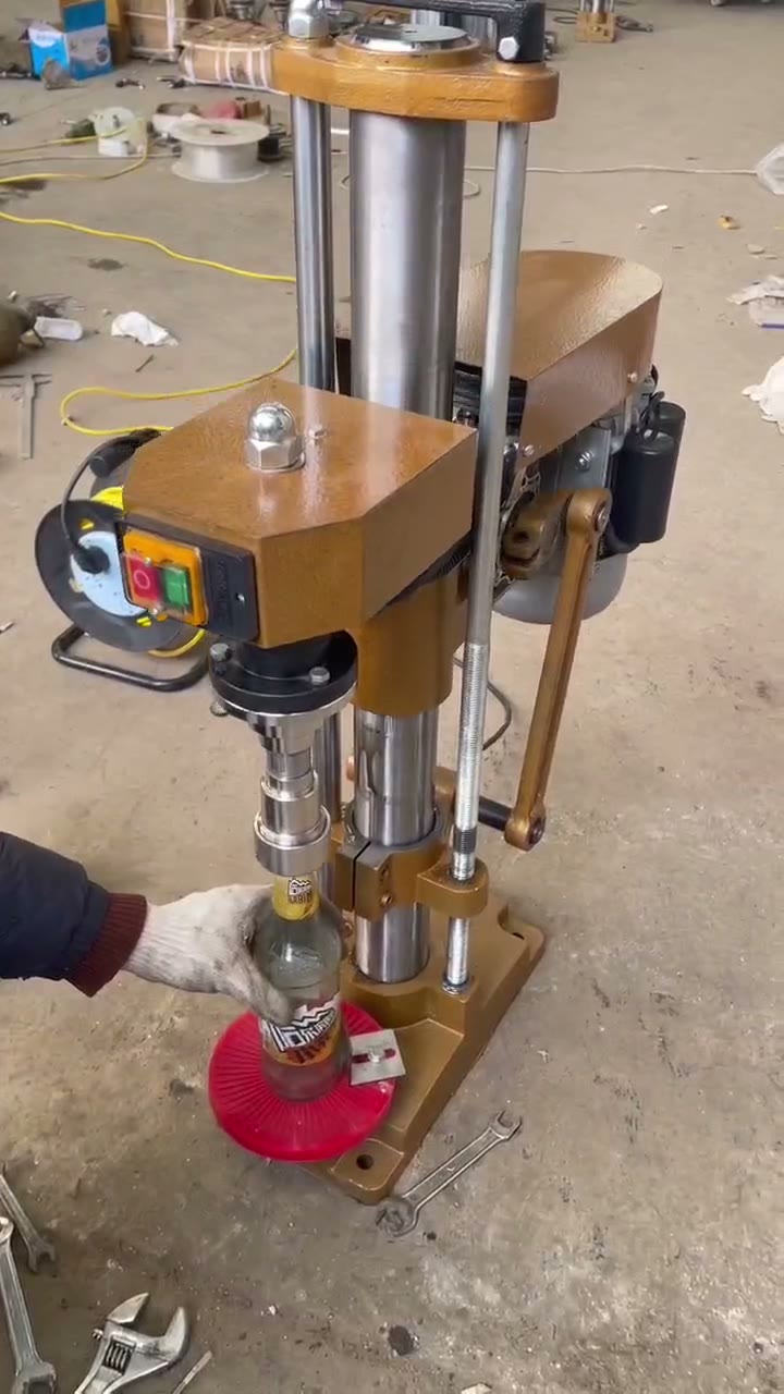
The TY-4 is a bench-mounted, column-type sealing machine for pilfer-proof aluminium closures. An operator holds the filled bottle on the bottle-support plate, the sealing head descends, and thread-forming and edge-rolling wheels form the closure directly onto the bottle neck. Because the cap is formed rather than screwed on, this machine suits ROPP-style aluminium caps, crown caps, and mineral-water caps — changed by swapping the press head.
Technical parameters
Published TY-4 specifications
The values below come from the manufacturer’s TY-4 operating manual. Confirm every dimension against your own bottle and cap before ordering, because the press head and sealing wheels are format-specific.
| Parameter | Published value |
|---|---|
| Bottle height range | 60–320 mm |
| Bottle mouth diameter | Ø16–50 mm |
| Output | 1,200 bottles per hour |
| Motor power | 0.37 kW |
| Overall dimensions | 380 × 700 × 950 mm |
| Height tolerance absorbed | Up to 50 mm variation, via the buffer device |
| Operation | Semi-automatic; operator loads and removes each bottle |
| Cap types | Pilfer-proof aluminium, crown, and mineral-water caps by changing the press head |
One published figure needs clarification before you quote
The manual lists “bottle height 60–320 mm” and also a second line reading “16–40 mm”, which is inconsistent as a height and most likely refers to cap height or cap diameter. Treat 60–320 mm as the working bottle-height range and ask us to confirm the second figure against your specific closure before purchase.
Machine in operation
How one sealing cycle actually runs
The operator places a filled bottle with the cap resting on the neck, the head comes down, and the sealing wheels roll the thread and skirt in a single stroke. Cycle rhythm depends on how quickly the operator loads and unloads.
Design features
What the buffer device and self-centring neck support are for
Buffer device on the bracket
Absorbs bottle-height variation within 50 mm so taller bottles are not crushed. The linkage shaft carries bevel blocks that release upward and re-close on the down stroke.
Self-centring bottle mouth
The neck locates itself under the head so sealing-wheel force is distributed evenly around the closure.
High sealing-head pressure
Adjustable pressure screws on both the thread wheels and edge wheels let you tighten the closure until it passes a leak check.
Quick format change
Swapping the press head adapts the machine to different cap styles and neck diameters, released by a single M6 socket bolt.
Buffer device caution from the manual
When all bottles in a batch are the same height, the bevel blocks must not actuate. If the buffer keeps triggering on uniform bottles, the setup is wrong — continuing will damage the machine and shorten its service life. Adjust the M8 nut only after confirming bottle height is genuinely inconsistent.
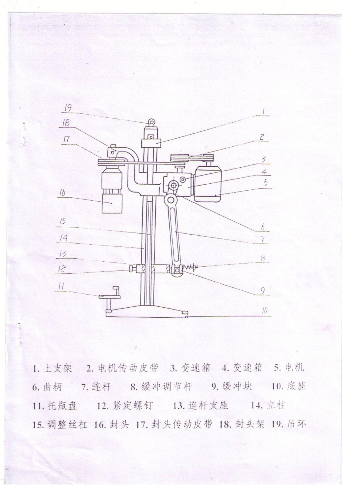
Figure 1 — general assembly
Main machine components
The drive runs from the motor through a belt and gearbox to a crank and connecting rod, converting rotation into the vertical stroke of the sealing head. Height is set with the adjusting screw on the column.
| No. | Component | No. | Component |
|---|---|---|---|
| 1 | Upper bracket | 11 | Bottle-support plate |
| 2 | Motor drive belt | 12 | Set screw |
| 3, 4 | Gearbox | 13 | Connecting-rod support |
| 5 | Motor | 14 | Column |
| 6 | Crank | 15 | Adjusting screw |
| 7 | Connecting rod | 16 | Sealing head |
| 8 | Buffer adjusting rod | 17 | Sealing-head drive belt |
| 9 | Buffer block | 18 | Sealing-head frame |
| 10 | Base | 19 | Lifting eye |
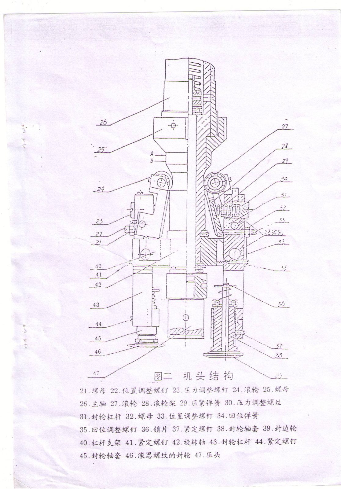
Figure 2 — sealing head structure
Where closure quality is actually set
The sealing head carries two thread-forming wheels and two edge-rolling wheels on lever arms, each with its own position screw and pressure screw. These four adjustments determine whether the closure seals, leaks, or scuffs the cap.
- 21, 25, 32 — nuts securing the lever assemblies
- 22, 33 — position adjusting screws
- 23, 30 — pressure adjusting screws
- 24, 27 — rollers; 28 roller frame
- 26 — main spindle
- 29 — compression spring; 34 return spring; 35 return adjusting screw
- 31, 43 — sealing-wheel levers; 40 lever bracket; 42 rotating shaft
- 36 — lock plate; 37, 41, 44 set screws
- 38, 45 — sealing-wheel bushings
- 39 — edge-rolling wheel; 46 thread-forming wheel; 47 press head
Installation and commissioning
Commissioning sequence from the manual
Height setting
Target 55–58 mm at bottom dead centre
Jog the machine to bottom dead centre, loosen set screw 12 at the front of the connecting-rod support, and turn the adjusting screw. With a capped bottle held against press head 47, set the gap from the bottle base to bottle-support plate 11 to roughly 55–58 mm, then retighten screw 12. Adjust from there based on actual results.
Wheel adjustment
Thread wheel into the groove, edge wheel under the neck
Turn the head by hand in the arrow direction and watch wheels 46 and 39. Loosen set screws 44 and 37, turn bushings 45 and 38 so thread wheel 46 enters the neck thread groove fully, and set edge wheel 39 to the lower face of the bottle mouth. If the seal is loose, adjust upward; if the cap shows scuffing, adjust downward.
Balance pressure on both sides
If thread or edge sealing is still loose, increase pressure at screws 23 and 30. The two thread wheels must carry similar pressure, and the two edge wheels must be equal — otherwise the finished cap will look different on each side. Note that the drawings show only one of each wheel; the symmetrical pair is not depicted.
Lubrication schedule
Manual lubrication points
| Ref. | Point | Oil | Interval |
|---|---|---|---|
| 16 | Eccentric block | 20# machine oil | 4× per shift |
| 18 | Main shaft sleeve | 20# machine oil | 4× per shift |
| 13 | Connecting-rod fixed shaft | 20# machine oil | 2× per shift |
| 16 | Sealing head | 20# machine oil | 2× per shift |
| 3 | Gearbox | 60# machine oil | Every 1,000 running hours |
Lubricate unlisted points as appropriate. All points are manual — there is no automatic lubrication system.
Supplied accessories
What ships with the machine
| Item | Qty |
|---|---|
| Sealing wheel | 1 |
| Thread-forming wheel | 1 |
| Tension spring | 2 |
Order wear parts against your cap format
Thread wheels, edge wheels, bushings, and press heads are format-specific. Confirm the exact cap drawing when ordering spares, and keep a spare set for each format you run.
Where the TY-4 fits
Good fit
- Small and mid-size edible-oil, sauce, vinegar, and beverage bottling at up to about 1,200 bottles per hour
- Pilfer-proof aluminium closures that must be formed onto the neck rather than screwed on
- Operations running several cap formats where a press-head swap is acceptable between batches
- Workshops with limited floor space and no compressed-air supply
- Batches with inconsistent bottle heights within a 50 mm band
Look elsewhere when
Not the right machine
- You need sustained output well above 1,200 bottles per hour — move to an inline chain-conveyor capper
- You need automatic cap sorting and feeding; the TY-4 relies on the operator placing each cap
- You need no-touch operation synchronised with an automatic filler and labeller
- Your closure is a plain plastic screw cap, which is better served by a torque-controlled screw capper
- Bottle mouth is outside Ø16–50 mm or bottle height falls outside 60–320 mm
Quotation checklist
What we need to confirm your format
- Bottle drawing and samples: material, overall height, body diameter, neck finish, thread, and support ring
- Cap drawing and samples: material, aluminium thickness, outer diameter, height, liner, and tamper band
- Number of different formats you intend to run on one machine
- Target sustained bottles per hour and shift pattern
- Actual bottle-height variation within a batch
- Supply voltage, frequency, and phase; plus destination country and documentation needs
- Acceptance criteria: removal torque, leak test, and tamper-band inspection standard
Send caps and bottles together
Sealing wheels and press heads are cut to the closure, so a cap drawing without the matching bottle is not enough to finalise tooling. Provide enough samples for setup trials, and agree the sample quantity and permitted defect rate before manufacture.
Related packaging equipment
Place sealing in the correct packaging route
Confirm the TY-4 against your bottle and cap
Send bottle and cap samples or drawings, your target output, batch height variation, supply voltage, and acceptance test. We will confirm press-head and sealing-wheel tooling before quoting.