Pneumatic multi-layer paper oil filter
Clarify pressed oil before storage, refining, or filling
This enclosed filter uses stacked replaceable filter paper, an integrated gear pump, and compressed-air assistance to separate suspended solids from crude edible oil. Choose the filtration area against the press schedule, oil condition, and required downstream flow.
Position in the oil line
Place filtration after pressing and before clean-oil handling
The filter is a clarification stage. It does not replace oilseed cleaning, correct pressing practice, settling where required, or a refining process selected for the finished-oil target.
Balance the filter against the press, not a headline capacity alone
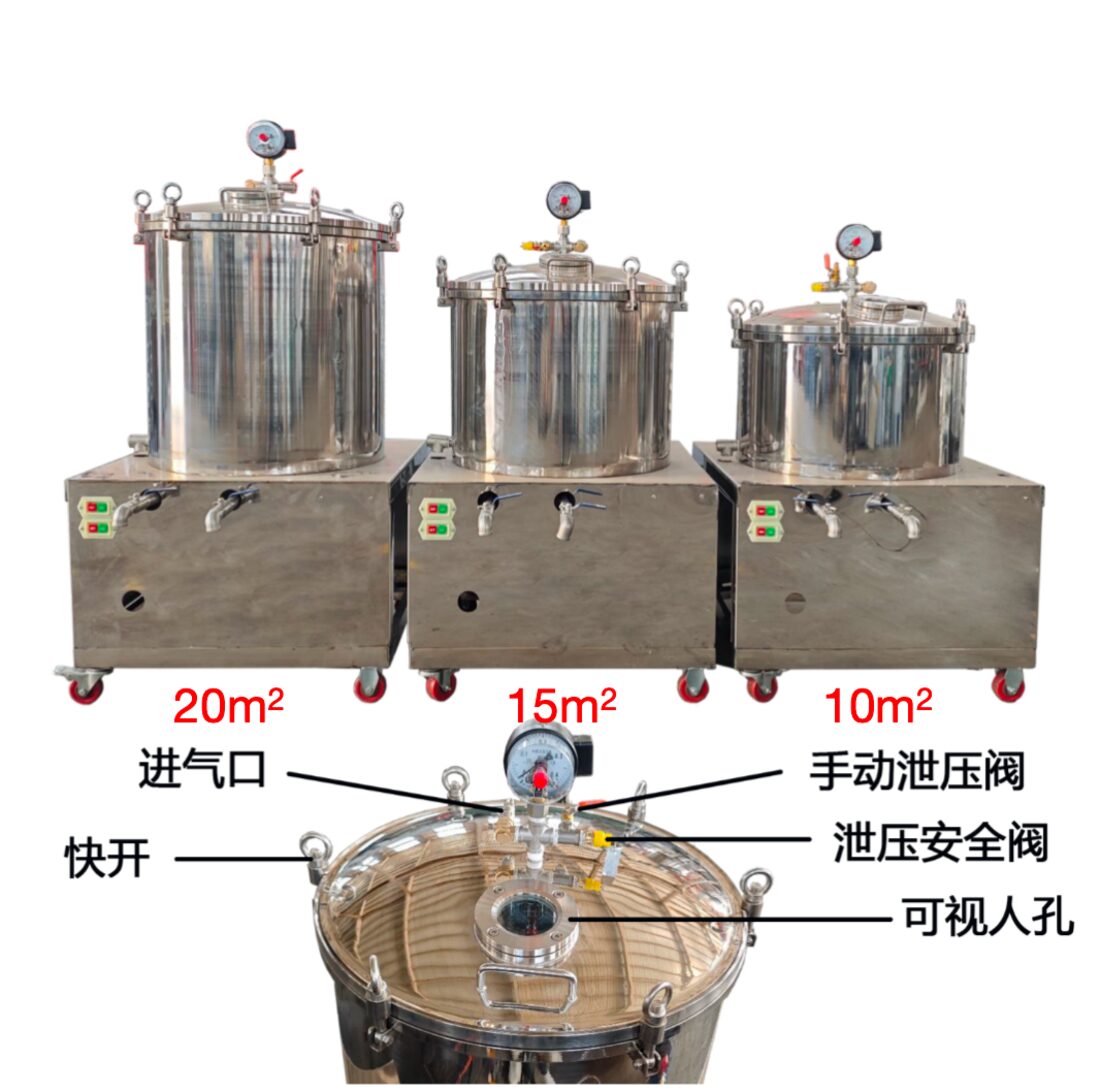
Oil temperature, viscosity, solids loading, paper grade, operating pressure, and filter-cake buildup all affect practical flow. Confirm the actual oilseed, pressing route, batch rhythm, and required clarity before selecting 10, 15, or 20 m².
Source-described construction
Integrated pumping, pressure assistance, and paper filtration
The current product page identifies these equipment features. Confirm the final material list, supplied accessories, and electrical package in the order specification.
Integrated utilities
The source lists a motor, gear pump, and air compressor on the machine, reducing the number of separate items required around the vessel.
Multi-layer filter paper
Replaceable paper layers provide the filtration surface and can be removed during cleaning and consumable replacement.
Quick-opening lid and sight port
The published design includes a quick-opening cover and a tempered-glass viewing port for observing the vessel without opening it.
Pressure protection
The source describes automatic stopping at the set pressure together with a separate pressure-relief safety valve.
Published model references
Compare filtration area, envelope, and nominal flow
These values reproduce the current page and should be treated as quotation references. Request a final drawing and a material-specific flow basis before line balancing.
| Filtration area | Overall dimensions | Design / working pressure | Published nominal capacity | Motor / compressor power |
|---|---|---|---|---|
| 10 m² | 1000 x 1000 x 1200 mm | 0.8 / 0.2 MPa | 100 kg/h | 1.1 kW |
| 15 m² | 1000 x 1000 x 1300 mm | 0.8 / 0.2 MPa | 150 kg/h | 1.1 kW |
| 20 m² | 1000 x 1000 x 1400 mm | 0.8 / 0.2 MPa | 250 kg/h | 1.1 kW |
Confirm vessel dimensions from the final drawing
The legacy table’s tank-height entries are ambiguously formatted, so they are not repeated here. The supplier drawing should identify vessel diameter, usable height, connection sizes, discharge clearance, and shipping dimensions.
Operating sequence
Separate the pumping stage from final air assistance
- Install the specified paper layers and inspect their seating before closing the vessel.
- Check the lid clamps, gasket, valves, gauge, relief device, and clean-oil outlet.
- Start the oil-suction pump first; the current instructions say not to start the air pump during initial filling.
- When oil flow falls near the end of the batch, stop the suction pump before applying air assistance as directed by the supplied manual.
- After filtration, isolate the machine, release all pressure, close the clean-oil route, and discharge residue.
Do not use webpage values as a commissioning procedure
Pressure-switch and gauge-pointer settings are safety-critical and must match the delivered controls. Use the machine manual, electrical diagram, and supplier commissioning instructions. Never loosen the lid or fittings while the vessel is pressurized.
Installation reference
Review assembly details before placing the machine
The existing video demonstrates the multi-layer pneumatic filter arrangement. Use it alongside the final layout to confirm access for paper replacement, residue discharge, clean-oil collection, electrical connection, and maintenance around the lid.
- Allow clearance above and around the quick-opening cover
- Keep the clean-oil outlet protected from dirty-side handling
- Provide a controlled route for residue and used filter paper
- Confirm floor loading, drainage, and safe caster locking
Consumables and sanitation
Specify paper, cleaning, and product-contact materials
- Filter-paper diameter, grade, quantity per stack, and expected replacement basis
- Paper support plates, gaskets, lid seal, and spare-seal part numbers
- Cleaning method for the vessel, pipework, pump, valves, and residue outlet
- Source-listed 304 stainless-steel contact surfaces and the brass top fitting
- Clean-water, cleaning-agent, wastewater, and used-paper handling plan
Buyer configuration checklist
Send the information that determines practical filtration
- Oilseed, hot- or cold-press route, and crude-oil sample or photos
- Oil temperature entering the filter and expected solids loading
- Press model, batch size, number of presses, and operating rhythm
- Required clean-oil destination: settling, refining, storage, or filling
- Voltage, frequency, phase, workshop layout, and destination country
Related production equipment
Connect the filter to the pressing and packaging schedule
Match the paper filter to the real pressing schedule
Send the oilseed, press model, crude-oil condition, batch rhythm, target clarity, downstream process, power supply, workshop dimensions, and destination country.