Hydraulic pressure FAQ
MPa, piston area, ton-force, chamber area, and output are different values
A pressure gauge does not show press tonnage or hourly production. This guide explains the relationship with a source-listed 60 MPa system and a legacy worked example using an approximately 260 mm piston diameter, while identifying the dimensions and units that still require drawing confirmation.
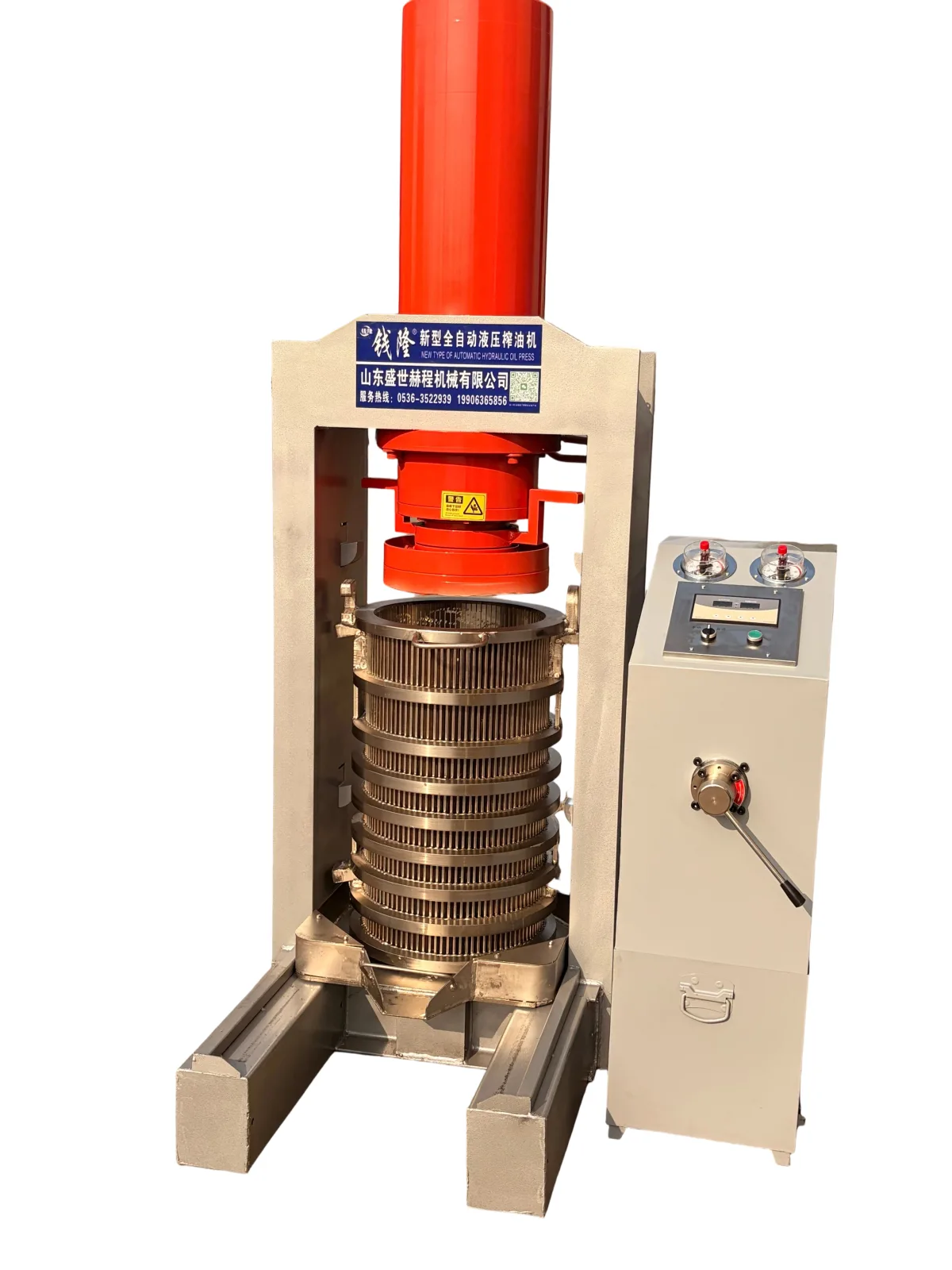
Definitions
Five values buyers should keep separate
They are connected, but they do not describe the same part of the machine or the same production result.
| Term | What it describes | How it is obtained | What it cannot tell you alone |
|---|---|---|---|
| System pressure, MPa | Fluid pressure at the measured point in the hydraulic circuit | Read from a suitable pressure gauge or transducer | Total actuator force, batch mass, cycle time, or hourly output |
| Piston area | The effective hydraulic area acted on by the pressure | Calculated from the effective piston diameter; rod-side area differs if applicable | Chamber volume or material loading |
| Press force | The ideal hydraulic force developed by pressure acting on effective piston area | Force = pressure x effective area | Uniform stress inside the cake or actual production rate |
| Chamber or cake area | The cross-sectional area across which the mechanical load is distributed | Calculated from the effective cake or chamber diameter | Hydraulic system pressure or usable batch mass |
| Output | Material processed or oil produced over a complete period | Measured from actual batches and the full operating cycle | It cannot be calculated from MPa or model tonnage alone |
Core equation
Pressure becomes force through piston area
F = P x A
For a circular piston, A = π x d2 / 4.
- F is force in newtons when SI units are used.
- P is hydraulic pressure in pascals; 1 MPa equals 1,000,000 Pa.
- A is effective piston area in square metres.
- d is effective piston diameter in metres.
- Metric ton-force is force divided by standard gravity: approximately 9.80665 kN per metric ton-force.
Use the effective hydraulic diameter
The pressing-chamber diameter does not create hydraulic force. Use the effective piston diameter from the cylinder drawing. If force is applied on the rod side of a double-acting cylinder, subtract the rod area from the piston area.
Worked example from the legacy page
60 MPa acting on an approximately 260 mm piston
The previous article supplied these two values but did not publish the cylinder drawing. The arithmetic below is valid for that assumed effective diameter; confirm the actual bore and operating side before treating it as the final machine calculation.
| Step | Calculation | Result | Interpretation |
|---|---|---|---|
| 1. Convert diameter | 260 mm = 0.260 m | Radius = 0.130 m | Assumed effective piston diameter from the legacy article |
| 2. Calculate area | π x 0.2602 / 4 | Approximately 0.0531 m2 | Ideal circular piston area |
| 3. Calculate force | 60,000,000 Pa x 0.0531 m2 | Approximately 3.19 MN | Ideal hydraulic force before practical losses or geometry questions |
| 4. Convert force | 3,185.6 kN / 9.80665 kN per metric ton-force | Approximately 324.8 metric ton-force | Consistent with a nominal 325-ton model designation if the assumed values are correct |
Calculation, not independent measurement
The result is calculated from the source-listed pressure and approximate piston diameter. It does not independently verify the real cylinder bore, calibration, relief-valve setting, mechanical losses, frame response, or force delivered during a material test.
Cylinder vs chamber
Why a 390 mm barrel is not the piston diameter
The current 300 / 325 product page lists a 390 mm diameter pressing barrel for the standard hot-press configuration and a separate 300 mm barrel option. Those dimensions describe the material chamber, not the hydraulic piston used in the force equation.
Total actuator force
Use hydraulic pressure and effective piston area. In the worked example, 60 MPa and 260 mm produce the calculated nominal force of approximately 324.8 metric ton-force.
Nominal average stress over the cake area
If the calculated force were distributed uniformly over a 390 mm diameter circle, the simple average would be approximately 26.7 MPa. Over a 300 mm circle it would be approximately 45.1 MPa.
These are geometric illustrations, not measured internal cake-pressure maps. Friction, clearances, material behavior, load transfer, and chamber construction affect the real stress distribution.
Gauge stages
Do not standardize by gauge color
The legacy page describes a blue gauge around 55 MPa and a red gauge around 60 MPa, using the lower stage for compaction and the higher stage for extraction. The current product page lists a 60 MPa system and a high-low dual-pump arrangement.
- Treat 55 MPa and 60 MPa as source-listed references for that described configuration.
- Gauge color is not a universal engineering standard or a substitute for the circuit diagram.
- Confirm gauge range, calibration, relief-valve settings, control logic, and allowed dwell time.
- Do not change pressure settings without the model-specific procedure and responsible technical approval.
No continuous-pressure guarantee is published here
The former article stated that the machine could remain at 60 MPa for long periods, but it did not provide a duty-cycle definition, temperature limit, component rating, test record, or maintenance condition. Confirm those limits in the supplied technical documentation.
Pressure vs production
Why MPa cannot predict real output
Output is a process measurement. Record the complete batch and operating period rather than multiplying pressure by chamber volume.
Source limitations
Numbers that need conditions or unit confirmation
| Published item | Current status | Required confirmation |
|---|---|---|
| 60 MPa system pressure | Listed on the current 300 / 325 product page | Operating setpoint, relief setting, gauge calibration, circuit location, and allowed duty cycle |
| Approximately 260 mm piston diameter | Appears in the legacy pressure article, not in the current product specification table | Cylinder drawing, effective bore, rod arrangement, tolerance, and model applicability |
| 300 / 325 tons down pressure | Listed as model force on the current product page | Calculation basis, effective hydraulic area, operating pressure, and whether the value is nominal or tested |
| Cake surface pressure listed as MPa/cm2 | The source unit is dimensionally inconsistent; values align more closely with a simple MPa area calculation | Correct unit, formula, effective cake area, and drawing basis |
| 5-100 kg press-volume range | Listed for the 390 mm hot-press barrel on the current product page | Oilseed, particle form, moisture, loading method, cycle settings, and acceptable cake condition |
| 60-70 kg working example | The legacy article presents it as an operating reference for a 390 mm chamber without test conditions | Material, preparation, barrel fill, cycle, target residual oil, and reason for the selected loading level |
Buyer checklist
Ask for enough data to reproduce the comparison
- Hydraulic schematic and cylinder drawing for the quoted model
- Effective piston bore, rod diameter where relevant, and operating side
- Normal setpoint, maximum allowed pressure, relief settings, and gauge range
- Barrel and effective cake dimensions, loading range, and source-unit correction
- Test material, preparation, batch mass, pressing time, and full cycle time
- Measured oil and cake results with the method and conditions disclosed
The safest comparison uses one calculation basis
Convert every supplier’s pressure, effective piston area, force, chamber area, batch basis, and complete cycle into the same units. Then compare the actual configuration and test conditions rather than model names alone.
Related pages
Continue from calculation to model and process selection
Restored original media
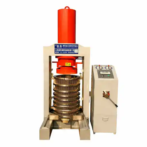
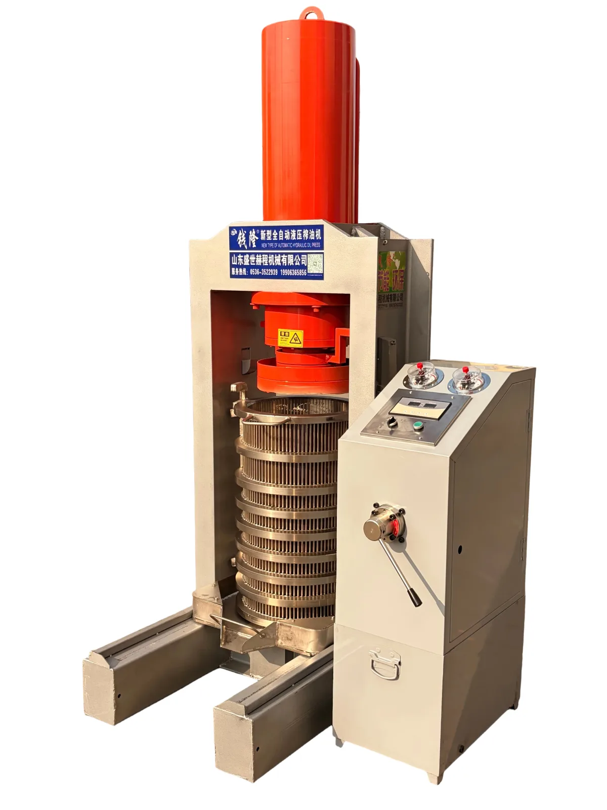
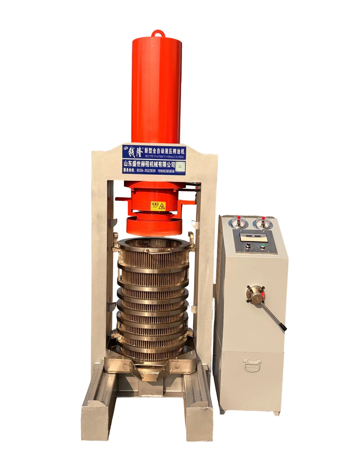
Hydraulic press construction photograph
Original machine photograph restored to the pressure and tonnage guide.
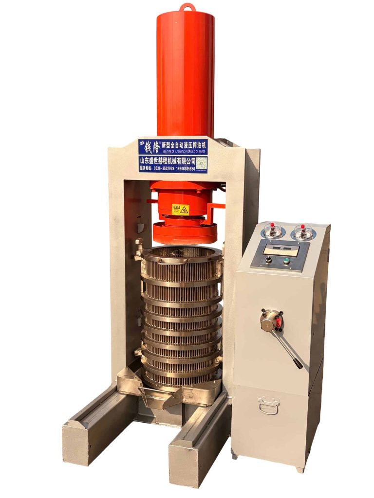
hydraulic oil press machine
Original photograph restored from the earlier page.
Request the drawing behind the pressure claim
Include the model, system pressure, claimed force, piston and chamber dimensions, raw material, target batch, and the exact unit or calculation that needs confirmation.