Controlled nitrogen dosing for packaging lines
Dose liquid nitrogen after filling and immediately before capping
The Cryo-VB300 injects a measured liquid-nitrogen dose into the available bottle headspace. The cryogenic liquid rapidly vaporizes into nitrogen gas, helping displace headspace air and support internal container pressure when the bottle, product, closure timing, and dose have been validated together.
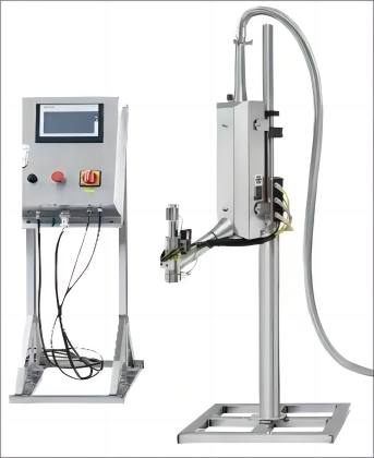
Standard reference configuration
Micro-dose control with PLC timing and bottle detection
These values come from the current equipment source. Final settings and achievable line speed must be confirmed with the actual container, headspace, capper distance, product temperature, and dosing mode.
0.01-14 g per cycle
Published adjustable liquid-nitrogen dosing range.
15-1000 ms
Published adjustable dosing-time range through the control recipe.
Up to 300 bottles/min
Maximum point-dosing speed stated for suitable applications.
Siemens control
PLC platform with a 7-inch touch-screen operator interface.
Line position
The dosing point sits between filling and closure application
Filler discharge, dosing-head position, conveyor movement, and capper timing must be coordinated so the container is sealed within the validated dosing window.
Packaging functions
Use nitrogen only after the package and process have been tested together
The final result depends on product temperature, available headspace, container material, closure timing, conveyor behavior, and the validated dose setting.
Headspace oxygen control
Vaporized nitrogen helps displace air in the bottle headspace for packaging plans involving oxidation-sensitive liquids.
Container pressure support
Nitrogen expansion after sealing can support the profile of compatible lightweight containers.
Line-speed synchronization
Bottle detection, PLC timing, and conveyor compensation coordinate each dose with container movement.
Adjustable recipes
Operators can set timing and dose targets for validated bottle, speed, and headspace combinations.
Working principle
Micro-dose the cryogenic liquid, then cap as it vaporizes
The machine doses liquid nitrogen rather than room-temperature nitrogen gas. Once the dose enters the container, it absorbs heat and changes rapidly into gas.
Closure timing is part of the dosing result
The filler, dosing unit, conveyor, and capper should be reviewed as one connected section. A dosing machine cannot compensate for uncontrolled headspace or an unsuitable delay before closure.
- Bottle detection: a sensor confirms the container position below the dosing head.
- PLC command: the selected recipe controls timing, nozzle actuation, and target dose.
- Liquid delivery: a controlled dose enters the available headspace.
- Immediate capping: the downstream capper closes the bottle within the validated interval.
- Nitrogen expansion: the liquid vaporizes and creates the planned headspace condition.
Cryo-VB300
Published technical specifications
The table preserves the current source values. Treat them as the standard reference configuration and confirm the final build, utilities, settings, and application performance before manufacture.
| Category | Specification | Published value |
|---|---|---|
| Machine | Model | Cryo-VB300 |
| Machine | Material | 304 stainless steel |
| Machine | Weight | 15 kg |
| Machine | Overall dimensions | 968 × 210 × 596 mm |
| Dosing assembly | Dosing-head dimensions | 294 × 51 mm |
| Dosing assembly | Dosing-arm length | 328 mm |
| Dosing assembly | Available nozzle sizes | 1.5 / 2.0 / 2.5 / 3.0 mm |
| Utilities | Liquid-nitrogen supply pressure | Below 0.15 MPa |
| Utilities | Nitrogen-gas supply | 0.5-0.65 MPa |
| Utilities | Power supply | 220 VAC, 50 Hz, 100 W |
| Thermal system | Liquid-nitrogen evaporation loss | Approximately 0.2 L/hour |
| Thermal system | Insulation | Vacuum insulated |
| Controls | Control platform | Siemens PLC |
| Controls | Operator interface | Siemens 7-inch touch screen |
| Dosing | Adjustable dosing time | 15-1000 ms |
| Dosing | Adjustable dose | 0.01-14 g per cycle |
| Dosing | Maximum point-dosing speed | Up to 300 bottles/min |
| Dosing | Maximum continuous-dosing speed | Up to 2,000 bottles/min, application dependent |
| Dosing | Accuracy | ±5% of the target dose |
| Interface | Languages | Chinese, English, Russian, Spanish, and Polish |
Supply-side equipment
Match the storage vessel and vacuum hose to the line layout
Runtime, local liquid-nitrogen supply, vessel location, hose routing, and the distance to the dosing head determine the project-specific supply package.
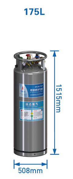
Storage vessel
175 L low-temperature tank
- Effective volume: at least 166 L
- Standard working pressure: 1.37 MPa
- Maximum working pressure: 1.59 MPa
- Diameter: 508 ± 2 mm
- Height: 1,515 mm
- Empty weight: approximately 108 kg
- Static evaporation: no more than 2.5 L/day
- Float-type level gauge and pressure gauge
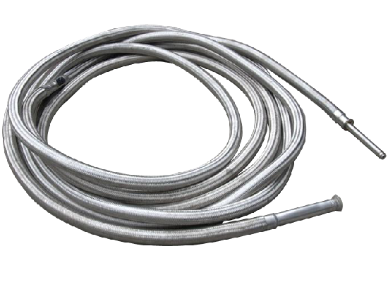
Transfer connection
DN10 vacuum-insulated hose
- Reference length: 4 m
- Connects the liquid-nitrogen vessel to the dosing unit
- Vacuum insulation helps limit heat gain and nitrogen loss
- Final length and fittings are confirmed from the line layout
Control and integration
Functions provided for automatic line operation
- Micro-dose control for small target amounts
- Conveyor speed synchronization and compensation
- Target-position dosing
- Fixed-speed dosing mode
- Adjustable dosing-head position
- Recipe control through the touch-screen interface
Project information
Data needed before the dosing section is configured
- Bottle material, volume, neck size, and available headspace
- Product type and filling temperature
- Target bottles per minute and operating schedule
- Distance from dosing point to cap application
- Liquid-nitrogen source, pressure, and expected runtime
- Conveyor height, speed control, and line communication requirements
- Required electrical standard and operator-interface language
- Workshop ventilation and cryogenic safety arrangements
Service support
Spare and wear parts for commissioning and routine maintenance
The final spare package should match the machine configuration and serial number. Recommended quantities depend on operating hours, local maintenance capability, and replacement-part lead time.
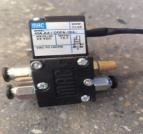
Solenoid valve
Controls liquid-nitrogen flow during each dosing command.
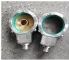
Heater
Helps control icing around the dosing assembly.

Sealing gasket
Maintains sealing at designated service connections.
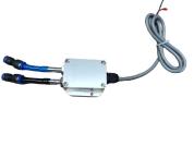
Detection sensor
Provides the trigger signal for timed bottle dosing.
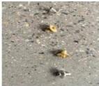
Dosing nozzle
Nozzle size is selected for the required dosing range.
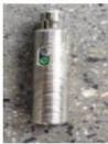
Photoelectric switch
Detects containers and line movement at the dosing point.

Proximity switch
Provides position feedback from moving components.
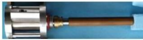
Pneumatic cylinder
Actuates the dosing mechanism where configured.
Cryogenic safety requirements
Liquid nitrogen must be handled by trained personnel. The installation area requires effective ventilation, suitable oxygen-deficiency monitoring, cryogenic personal protective equipment, and pressure-rated vessels, hoses, valves, and fittings. The completed installation must comply with local safety codes.
Maintenance planning
Identify every replacement part against the supplied machine
- Record the equipment serial number and installed component model.
- Keep sealing parts and nozzles clean and correctly packaged.
- Inspect hoses, fittings, sensors, and icing condition during planned stops.
- Use only components matched to the pressure, temperature, and control requirements.
- Confirm replacement parts against the nameplate before ordering.
Related packaging equipment
Build the dosing point into the wider filling and capping line
Confirm the dosing system against the actual bottle and line
Send the bottle drawing, product temperature, headspace, target output, capper position, conveyor details, utility conditions, liquid-nitrogen supply plan, and required runtime.