Closure application after edible-oil filling
Match the capping method to the real bottle, cap, and required line rhythm
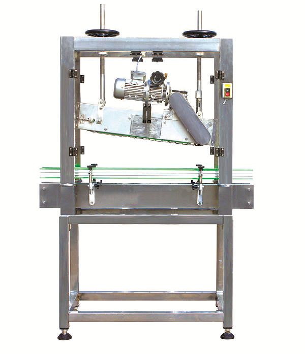
This page covers capping as a packaging function rather than one fully specified model. The current source describes both semi-automatic and automatic solutions, while the hosted image shows one inline capping machine. Final selection requires bottle and cap samples or approved drawings.
Buyer decisions
Closure geometry and presentation determine the machine
A nominal bottle volume is not enough. Cap style, thread, liner, tamper feature, neck finish, bottle rigidity, and how the cap reaches the bottle all change the required handling and tightening arrangement. If the closure is a roll-on aluminium or pilfer-proof cap rather than a pre-formed screw cap, see the TY-4 cap sealing machine, which rolls the thread onto the bottle neck instead of tightening a finished cap.
Cap presentation
State whether caps are placed by an operator or automatically sorted, fed, and applied.
Bottle control
Confirm guides, spacing, stabilization, neck support, and conveyor behavior for every format.
Tightening result
Define applied-torque and seal-inspection criteria with the closure supplier.
Line boundary
Identify who supplies the conveyor, cap feeder, capper, sensors, guards, and reject handling.
Packaging sequence
Control the interval between filling, cap placement, and tightening
The capping section begins with a correctly filled, clean container and ends with an inspected closure. Any nitrogen-dosing step must be coordinated between filling and cap application.
Automation boundary
Decide who handles the bottle and who presents the cap
| Decision | Semi-automatic arrangement | Automatic line arrangement |
|---|---|---|
| Bottle handling | The source describes manual bottle positioning. | Bottles move through a conveyor-based workflow. |
| Cap presentation | Confirm whether the operator places each cap before tightening. | Confirm whether cap sorting, feeding, and placement are included or separately supplied. |
| Production rhythm | Depends heavily on operator handling and pack format. | Depends on the slowest connected module and the approved bottle/cap combination. |
| Changeover | Usually involves manual adjustment and sample checks. | May require guides, heads, feeders, sensors, recipes, and format parts. |
| Best-fit question | Is flexible small-batch operation more important than continuous transport? | Must capping synchronize with automatic filling, labeling, coding, and packing? |
What the current source establishes
Published capabilities are broad; the machine data sheet is still missing
- The page describes semi-automatic and automatic capping solutions.
- It describes adjustable torque control but publishes no torque range or verification method.
- It lists 100, 250, and 500 mL, 1 L, 2 L, and 5 L bottles as typical packaging examples.
- It states that the capper can integrate with filling, conveyor, labeling, coding, and carton equipment.
- It publishes no model number, speed, cap range, bottle range, dimensions, power, air demand, material schedule, or changeover time.
Do not treat the example bottle sizes as a guaranteed range
A 500 mL bottle and another 500 mL bottle can require different guides, support, cap handling, and tightening because their shapes, necks, caps, wall stiffness, and filled weights differ.
Bottle and cap compatibility
Approve the complete closure system
- Bottle material, shape, overall height, body diameter, base stability, and filled weight
- Neck finish, opening, thread, support ring, and dimensional tolerances
- Cap material, outer diameter, height, thread, liner, tamper band, and surface texture
- Required applied torque, removal torque, leak test, and visual acceptance criteria
- Cap orientation and presentation method, including bulk cap handling where required
- Oil contamination controls around the neck and closure before tightening
Product boundary
Edible oil type does not define capper compatibility
The source lists sesame, peanut, soybean, sunflower, rapeseed, tea-seed, and other edible oils. These oil names describe the filled product, but the capper is primarily selected around package geometry, closure behavior, line speed, and the condition of the bottle entering the capping zone.
Send physical samples for a trial
Provide enough empty bottles, caps, liners, tamper components, labels, and representative filled weight for setup and testing. Drawings alone may not reveal bottle deformation or cap feeding behavior.
Line integration
Define signals and accumulation on both sides of the capper
A capping machine cannot stabilize an unsuitable bottle, correct oil on the neck, or compensate for uncontrolled bottle spacing. Review the filler discharge and downstream labeler as part of one transfer section.
Upstream filler
Confirm bottle spacing, fill height or weight, drip control, neck cleanliness, and conveyor handoff.
Cap supply
Specify manual placement or the required sorter, elevator, chute, feeder, and low-cap alarm.
Capping zone
Approve bottle guides, stabilizers, tightening components, guards, sensors, and reject logic.
Downstream transfer
Plan inspection, label application, coding, accumulation, carton packing, and stop signals.
Controls and utilities
Obtain missing utility data before layout approval
- Model-specific electrical voltage, frequency, phase, connected load, and protection
- Compressed-air pressure, flow, quality, and connection if the selected mechanism is pneumatic
- Conveyor height, speed range, direction, width, and upstream/downstream control signals
- Capper adjustment method, recipes, alarms, counters, and operator-interface language
- Emergency stops, guards, access switches, safe restart, and line-stop behavior
- Installed dimensions, service clearances, cap-loading access, and floor requirements
Maintenance and safety
Inspect wear parts against closure quality
- Isolate electrical, pneumatic, conveyor, and stored mechanical energy before service.
- Inspect tightening belts, wheels, chucks, guides, sensors, bearings, and drive components as fitted.
- Keep cap-contact parts clean and free from oil that can change grip or applied torque.
- Record setup values and sample-test closure performance after maintenance or changeover.
- Order spares against the final capper model, cap feeder, and approved bottle formats.
Quotation checklist
Provide the closure data that controls the design
- Bottle and cap drawings plus physical samples for every intended format
- Cap material, liner, tamper feature, thread, and closure-supplier specifications
- Required applied torque, leak-test method, and visual inspection standard
- Target sustained bottles per minute and the upstream filler discharge pattern
- Manual or automatic cap placement and the required cap storage duration
- Workshop layout, utilities, conveyor data, destination, and documentation needs
Final acceptance needs a defined test
Agree the bottle and cap lot, line speed, setup, sample quantity, applied-torque or removal-torque method, leak test, tamper-band inspection, and permitted defects before manufacture.
Related filling equipment
Place closure application in the correct packaging route
Approve the closure system with real bottles and caps
Send samples, drawings, closure specifications, required torque and leak tests, target output, upstream and downstream equipment, utilities, workshop layout, and destination country.